This page provides a brief, high-level overview of my Bachelor’s thesis written at RWTH Aachen. While this page focuses on the implementation-based part of our prototype, more details on user studies and their results are available in a follow-up paper.
The full PDF is available here and the code to our prototype is accessible on my GitHub.
Abstract:
Augmented Reality (AR) applications for handheld devices are gaining popularity every year. Conventionally in handheld AR, an image of the real world is captured by a camera on the back of the device. Afterwards, the image is augmented with virtual information and displayed on the screen. This process, called device-perspective rendering (DPR), introduces misalignments between the displayed image and the view of the user (see right side of Figure 1). User-perspective rendering (UPR) is an alternative rendering method that eliminates this misalignment by rendering the displayed image from the perspective of the user. For this, in addition to the position of the device, the position of the user’s eyes is tracked. There are advantages and disadvantages to both rendering methods, which means that for some applications neither DPR nor UPR would be the perfect choice. The aim of this thesis is to introduce new rendering methods that fill the gap between UPR and DPR by combining advantages from both sides. After analyzing the trade-off between UPR and DPR in more detail, this thesis lays out the implementation of three new methods. The implementation results in an application for iOS devices, which acts as a prototype for the new rendering methods. This prototype may be used to compare them to UPR and DPR in user studies, examples of which are presented at the end of this thesis. Therefore, the prototype will be helpful for future research and applications in the field of handheld AR.
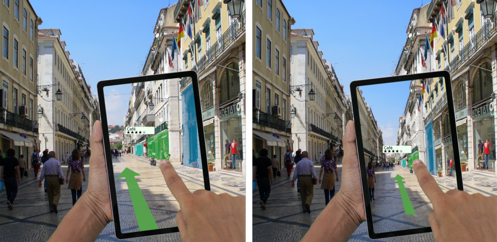
Fig. 1: Illustration of the differences between UPR (left) and DPR (right)
Geometric Setup for UPR:
Our implementation is based on the general setup as illustrated in Figure 2. It is inspired by the geometric approach by [Samini and Palmerius, 2014]. Some implementation details are different, and we improve upon it by making it work more accurately at small distances.
The live video captured by the device’s physical camera is displayed on the virtual image plane (light grey Fig. 2). Afterwards, the view of a virtual camera (positioned at the useres eyes) is rendered on the device’s screen. This results in a transparency effect because the frustum corners of the virtual camera are aligned with the screen corners of the device. The virtual camera looks “through” the screen and displays what the user would see behind it. The trick is for the image plane to be correctly positioned in the virtual space.

Fig. 2:
The main components of our implementation: i) the screen of the device, ii) the virtual image plane depicting the most recent image captured by the device’s camera, and iii) the frustum of the virtual camera, originating from the position of the user’s eyes.
Positioning the Image Plane:
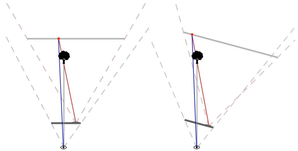
Fig. 3:
Correct position and size of the image plane results in an approximately correct alignment between the on-screen content (blue line) and the view of the user (grey line).
The image plane’s relative position and orientation to the device will directly influence which part of the captured image is inside the virtual frustum. For the desired transparency effect, objects redered on the screen must appear to the user in the same sizes and positions as they do in the real world. To achieve this, the image plane is positioned straight behind the device’s camera and acts as a “two-dimensional slice” of its frustum in the virtual scene. It is important that the image plane matches the width of the frustum of the device’s physical camera. With its size set to 10×13.33 meters, the distance from the device’s camera is determined by the camera intrinsics or FOV (roughly 10m for the devices we tested on, which is equivalent to a FOV of approximately 60 degrees).
Moving the Image Plane back to correct for sizing errors:
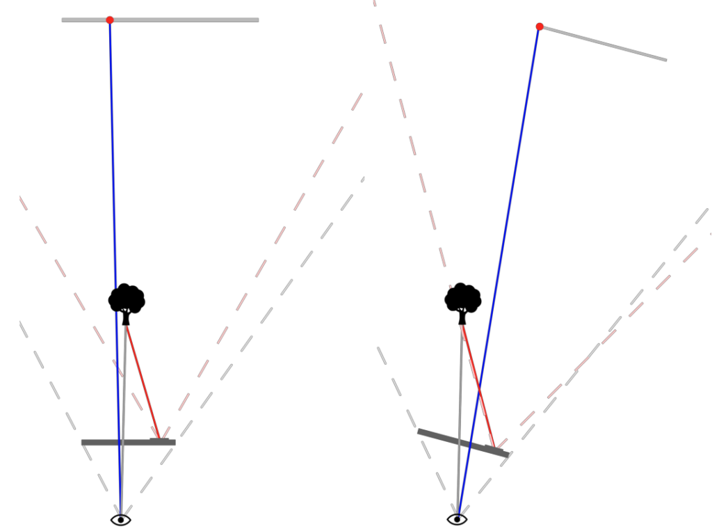
Fig. 4:
Moving the image plane back results in misalignments when looking at the screen from the side.
The naive approach described above works as long as the distance between the user’s eyes and the device is negligible compared to that between the device and the observed object. In small environments however, where the observed scene is less than two meters away from the device, objects tend to appear too big on screen. To counteract this problem, the distance between image plane and device is increased when the depth of the scene becomes too small. The depth of the scene is measured using the device’s LiDAR sensor.
Moving the image plane back however, introduces new misalignments when looking at the screen from the side (see Fig. 4). The error results out of the fact that the image plane is now too small to cover the width of the camera frustum.
Restoring alignment between on-screen content and real-world objects:
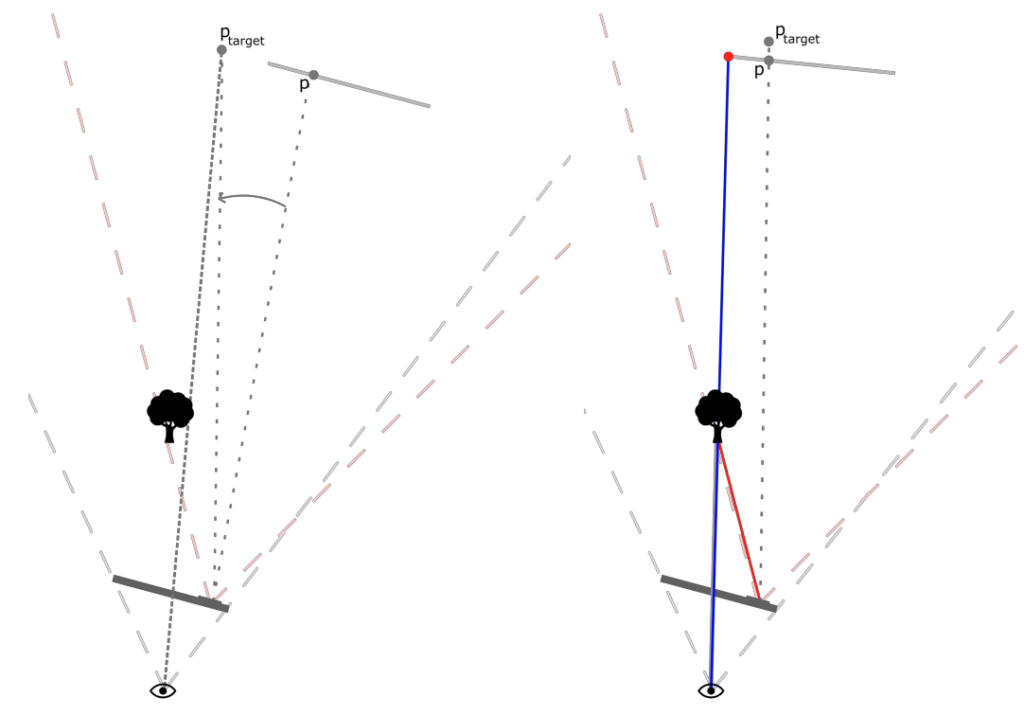
Fig. 5:
To restore the alignment between on-screen content and real-world objects, the image plane is rotated around the position of the device’s camera.
To keep the right part of the image displayed on screen, the image plane is rotated around the position of the device’s camera. The amount of rotation is dependent on both the angle at which the user looks at the screen and the distance to the image plane. Following the sight of the user through the center of the screen, a point p_target is determined at the distance of the image plane. If the image plane covered the entire width of the camera frustum, the point p_target would refer to the point p on the image plane. To adjust the position of the image plane, it is rotated around the device’s camera until p lies on the line of p_target.
New Rendering Methods:
In addition to standard DPR and the (approximated) UPR method explained above, we implemented three new rendering methods. These methods differ from our UPR implementation in the position of the virtual camera and the shape and orientation of its frustum.
The first method (Fig. 6) renders the scene from the user’s perspective with an increased FOV. This is achieved by artificially increasing the size of the screen, moving its corners outwards. The on-screen content stays fully responsive to changes in the position of the user’s head. Additionally, the bigger FOV allows for more AR-contenct to be displayed, while the misalignment between on-screen content and surroundings is relatively small.
The second method (Fig. 7) renders the scene from the position of the device’s camera but responds to changes in the user’s head position by rotating its frustum. This method benefits from the biggest FOV, which is the same as in DPR. Normally, not the whole camera image can be displayed at once, as it has an aspect ratio of 4:3; the screen itself is narrower. By rotating the camera frustum when the user is looking at the screen from the side, this rendring method makes use of the additional image space that would normally go unused.
The third method (Fig. 8) interpolates between the POVs and frustum shapes of UPR and DPR. It merges the two rendering methods. When interpolating between them, the position of the virtual camera is placed on a line between the user’s eyes and the device’s camera, while the frustum corners are moving from the screen corners to the corner points on the image plane.
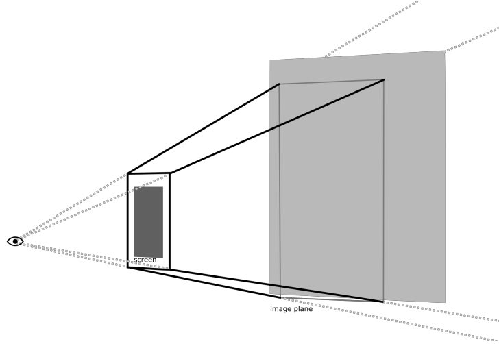
Fig. 6: UPR with increased FOV
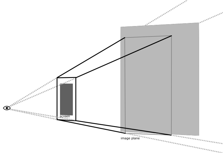
Fig. 7: “reactive” DPR
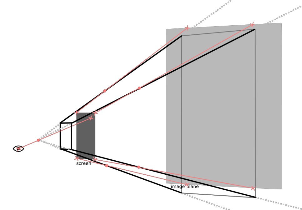
Fig. 8: Interpolation between UPR and DPR
Summary:
Handheld devices are one of the most common ways in which AR is used today. In handheld AR, the combination of real-world view and virtual information is achieved by superimposing the virtual scene onto an image of the real world. This image is captured by a camera on the back of the device, which is why this process is called device-perspective rendering (DPR). It results in a misalignment between what is displayed on screen and the view of the user because the displayed image is completely dependent on the position and orientation of the device. In user-perspective rendering (UPR), on the other hand, the position of the user’s eyes is taken into account and the displayed image is rendered from the perspective of the user. UPR comes with benefits and drawbacks, which creates a trade-off between itself and DPR. In this thesis, three new rendering methods are introduced. They aim to combine the advantages of DPR and UPR by combining aspects from both sides. These new rendering methods – including approximated UPR and DPR – were implemented in the form of an application for iOS. The prototype was built in Unity and is intended to enable direct comparisons between different rendering methods. To the best of our knowledge it is the first to work without requiring any additional hardware and runs on of-the-shelf consumer smartphones and tablets. This makes our implementation of these rendering methods accessible for future applications and research in the field of handheld AR.